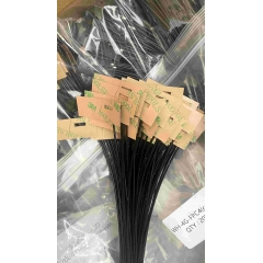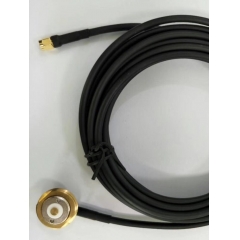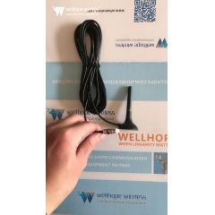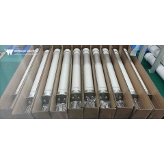

 Antena routera WiFi.
Polaryzacja anteny: czym jest i dlaczego ma znaczenie
Szacowany czas czytania: 15 minut
Każdy inżynier elektroniki wie, że anteny transmitują i odbierają sygnały w postaci fal elektromagnetycznych (fal energii elektromagnetycznej), których właściwości można opisać za pomocą równań Maxwella. Podobnie jak wiele specjalistycznych zagadnień technicznych, możemy interpretować te równania wraz z zasadami propagacji i charakterystykami fal elektromagnetycznych z wielu perspektyw — od stosunkowo prostych opisów jakościowych po złożone, rozbudowane wzory matematyczne.
Polaryzacja jest jedną z wielu charakterystyk propagacji energii elektromagnetycznej. Jej wpływ oraz stopień, w jakim należy ją uwzględniać, znacznie różnią się w zależności od różnych scenariuszy zastosowań i odpowiadających im konstrukcji anten. Podstawowe zasady polaryzacji dotyczą całego promieniowania elektromagnetycznego, w tym sygnałów radiowych (RF)/bezprzewodowych oraz energii fal świetlnych, a polaryzacja znajduje szerokie zastosowanie w dziedzinie optyki. Ten artykuł obejmuje wyłącznie pasmo częstotliwości RF.
Czym jest polaryzacja anteny?
Aby zrozumieć polaryzację, należy najpierw opanować podstawy fal elektromagnetycznych. Fala elektromagnetyczna składa się z pola elektrycznego (pole E) i pola magnetycznego (pole H) poruszających się w tym samym kierunku. Pole elektryczne i pole magnetyczne są względem siebie prostopadłe, a oba są prostopadłe do kierunku propagacji fali płaskiej.
Polaryzację definiuje się jako płaszczyznę drgań pola elektrycznego obserwowaną od strony nadajnika w kierunku rozchodzenia się fali. Przy polaryzacji poziomej pole elektryczne oscyluje na boki w płaszczyźnie poziomej; przy polaryzacji pionowej pole elektryczne drga w górę i w dół w płaszczyźnie pionowej (patrz rysunek 1).

Rysunek 1: Fala elektromagnetyczna z wzajemnie prostopadłymi składowymi pola elektrycznego i magnetycznego
Anteny nadawcza i odbiorcza tworzą parę anten , a wydajność nadajnika-odbiornika osiąga maksimum, gdy obie mają identyczne płaszczyzny polaryzacji. Nawiązując do kultowej kwestii z filmu Obcy z 1979 roku — „W kosmosie nikt nie usłyszy twojego krzyku” — w przestrzeni kosmicznej nie istnieje żadna wrodzona różnica między polaryzacją poziomą i pionową. Mimo to teorie dopasowania polaryzacji i ustawienia anten nadal pozostają prawdziwe dla maksymalizacji transmisji i odbioru energii sygnału.
Polaryzacja liniowa i kołowa
Fale elektromagnetyczne charakteryzują się wieloma trybami polaryzacji:
- Podstawowa polaryzacja liniowa obejmuje dwie wzajemnie ortogonalne (prostopadłe) formy polaryzacji (patrz rysunek 2). Teoretycznie poziomo spolaryzowana antena odbiorcza nie może przechwycić żadnego sygnału emitowanego przez pionowo spolaryzowaną antenę nadawczą pracującą na tej samej częstotliwości i odwrotnie. Im bliższe są orientacje polaryzacji obu anten, tym silniejszy jest odbierany sygnał; wydajność transferu energii sygnału osiąga maksimum przy idealnym dopasowaniu polaryzacji.

Rysunek 2: Polaryzacja liniowa oferuje dwie wzajemnie ortogonalne formy polaryzacji
- Polaryzacja skośna jest odmianą polaryzacji liniowej. Podobnie jak standardowa polaryzacja pozioma i pionowa, definicja ta dotyczy wyłącznie scenariuszy naziemnych. Polaryzacja skośna tworzy kąt ±45° względem płaszczyzny poziomej. Chociaż polaryzacja skośna jest zasadniczo liniowa, gdy specjaliści branżowi odnoszą się do „polaryzacji liniowej”, zwykle mają na myśli wyłącznie anteny o polaryzacji poziomej lub pionowej.
- Sygnały emitowane lub odbierane przez anteny o polaryzacji skośnej mogą być przechwytywane przez anteny wyłącznie poziomo lub pionowo spolaryzowane, choć z pewną stratą sygnału. Anteny o polaryzacji skośnej są idealne w zastosowaniach, w których stan polaryzacji jednej lub obu anten jest nieznany albo gdy polaryzacja zmienia się podczas pracy.
- Polaryzacja kołowa (CP) jest bardziej złożona niż polaryzacja liniowa. W tym trybie polaryzacji wektor pola elektrycznego stale się obraca podczas propagacji sygnału. Patrząc od strony nadajnika na zewnątrz, obrót wektora pola elektrycznego zgodny z ruchem wskazówek zegara nazywa się prawoskrętną polaryzacją kołową (RHCP); obrót przeciwny do ruchu wskazówek zegara to lewoskrętna polaryzacja kołowa (LHCP) (patrz rysunek 3).

Rysunek 3: Wektor pola elektrycznego fal elektromagnetycznych o polaryzacji kołowej obraca się, dzieląc się na typ prawoskrętny i lewoskrętny
Sygnały o polaryzacji kołowej powstają przez nałożenie dwóch ortogonalnych fal elektromagnetycznych z przesunięciem fazowym 90°. Aby wytworzyć polaryzację kołową, muszą być spełnione trzy warunki: pole elektryczne musi zawierać dwie ortogonalne składowe; obie składowe muszą mieć różnicę faz 90°; a obie składowe muszą mieć jednakową amplitudę. Anteny śrubowe stanowią proste rozwiązanie do generowania fal o polaryzacji kołowej.
- Polaryzacja eliptyczna (EP) jest pochodną polaryzacji kołowej. Podobnie jak fale o polaryzacji kołowej, fale o polaryzacji eliptycznej są tworzone z dwóch fal o polaryzacji liniowej. Polaryzacja eliptyczna powstaje, gdy nałożone zostaną dwie wzajemnie prostopadłe fale o polaryzacji liniowej i nierównych amplitudach.
Stopień niedopasowania polaryzacji między dwiema antenami jest określany ilościowo przez współczynnik strat polaryzacyjnych (PLF), mierzony w decybelach (dB). Jego wartość zależy od kąta polaryzacji między anteną nadawczą i odbiorczą. Teoretycznie PLF wynosi 0 dB przy idealnym dopasowaniu polaryzacji (brak strat); jeśli obie anteny są całkowicie ortogonalnie spolaryzowane, PLF dąży do nieskończoności (całkowite tłumienie sygnału).
W rzeczywistych zastosowaniach anteny nie mogą jednak osiągnąć idealnie dopasowanej ani całkowicie ortogonalnej polaryzacji. Niewłaściwe ustawienie mechaniczne podczas instalacji, błędy obsługi, zniekształcenia kanału, odbicia wielodrogowe i inne czynniki wprowadzają odchylenia kątowe kierunku polaryzacji transmitowanego pola elektrycznego. Nawet jeśli dwie anteny są zaprojektowane dla ortogonalnej polaryzacji, w praktyce nadal występuje przeciek polaryzacji krzyżowej na poziomie 10 do 30 dB lub wyższym. W niektórych scenariuszach ten przeciekający sygnał jest wystarczająco silny, aby zakłócać demodulację pożądanego sygnału.
Z drugiej strony, nawet przy idealnej polaryzacji i precyzyjnym ustawieniu dwóch anten, rzeczywiste czynniki środowiskowe mogą zwiększyć PLF do 10 dB, 20 dB lub więcej, pogarszając odbiór sygnału. Mówiąc prosto, niezamierzona polaryzacja krzyżowa i wysokie współczynniki strat polaryzacyjnych powodują dwa niekorzystne skutki: wprowadzają sygnały zakłócające i zmniejszają siłę docelowego użytecznego sygnału.
Dlaczego charakterystyka polaryzacji ma znaczenie
Polaryzacja podlega zasadzie dwukierunkowej: im dokładniej wyrównane i zgodne są typy polaryzacji dwóch anten, tym większa jest siła odbieranego sygnału. Z kolei słabe dopasowanie polaryzacji utrudnia zarówno docelowym odbiornikom, jak i odbiornikom zakłóceń przechwytywanie wystarczającej ilości użytecznych sygnałów. W większości scenariuszy kanał bezprzewodowy zmienia stan polaryzacji transmitowanego sygnału albo jeden lub oba nadajniki-odbiorniki nie mogą utrzymać stałej, nieruchomej orientacji anteny.
Wybór trybu polaryzacji jest zazwyczaj określany przez środowisko instalacji i warunki propagacji atmosferycznej. Na przykład anteny o polaryzacji poziomej zapewniają lepszą wydajność sygnału i bardziej stabilną polaryzację, gdy są montowane w pobliżu sufitów; natomiast anteny o polaryzacji pionowej instalowane przy ścianach bocznych wykazują charakterystykę polaryzacji bliższą swoim nominalnym specyfikacjom projektowym.
Typowe anteny dipolowe (standardowe dipole / dipole składane) działają z polaryzacją poziomą przy konwencjonalnym montażu (patrz rysunek 4). Jeśli wymagane jest dopasowanie do określonego trybu polaryzacji, antenę można obrócić o 90°, aby przełączyć ją na polaryzację pionową (patrz rysunek 5).
SHAPE \* MERGEFORMAT
Rysunek 4: Anteny dipolowe są zazwyczaj montowane poziomo na masztach dla uzyskania polaryzacji poziomej
SHAPE \* MERGEFORMAT
Rysunek 5: Anteny dipolowe można instalować pionowo na masztach w celu uzyskania polaryzacji pionowej, gdy wymaga tego zastosowanie
Polaryzacja pionowa jest szeroko stosowana w ręcznych radiotelefonach, takich jak urządzenia przenoszone przez personel ratownictwa. Wynika to z faktu, że większość pionowo spolaryzowanych anten radiowych charakteryzuje się dookólnymi charakterystykami promieniowania — co oznacza, że użytkownicy nie muszą korygować azymutu anteny, nawet gdy orientacja urządzenia przenośnego stale się zmienia.
Większość anten pracujących w paśmie wysokiej częstotliwości (HF) 3–30 MHz wykorzystuje proste konstrukcje anten długodrutowych rozciągniętych poziomo między podporami. Ich duży rozmiar fizyczny wynika z odpowiadającej im długości fali (10–100 metrów), a takie anteny są z natury spolaryzowane poziomo.
Co ciekawe, pasmo to nazwano „wysoką częstotliwością” kilkadziesiąt lat temu, gdy 30 MHz było uznawane za zakres wysokich częstotliwości. Chociaż obecnie nazwa ta wydaje się przestarzała, pozostaje oficjalnym oznaczeniem pasma określonym przez Międzynarodowy Związek Telekomunikacyjny (ITU) i nadal jest powszechnie używana.
Pasmo fal średnich (MW) obejmuje zakres od 300 kHz do 3 MHz. Polaryzacja wybierana przez stacje nadawcze w tym paśmie zależy od tego, czy stacja wykorzystuje fale przyziemne do krótkiego zasięgu i silnego pokrycia sygnałem, czy fale jonosferyczne do transmisji na duże odległości. Ogólnie rzecz biorąc, anteny spolaryzowane pionowo zapewniają lepszą propagację fal przyziemnych, natomiast anteny spolaryzowane poziomo są lepiej przystosowane do łączności z wykorzystaniem fal jonosferycznych.
Łączność satelitarna w dużym stopniu opiera się na polaryzacji kołowej. Satelity nieustannie zmieniają swoje położenie względem stacji naziemnych i innych satelitów. Wydajność transmisji sygnału osiąga maksimum, gdy zarówno nadajnik, jak i odbiornik wykorzystują anteny spolaryzowane kołowo; połączenie anten spolaryzowanych liniowo z antenami spolaryzowanymi kołowo jest możliwe, ale powoduje mierzalny współczynnik strat polaryzacyjnych.
Charakterystyki polaryzacji są równie istotne dla systemów 5G. Niektóre układy antenowe 5G Multiple-Input Multiple-Output (MIMO) wykorzystują technologię polaryzacji w celu bardziej efektywnego wykorzystania zasobów widma, zwiększając szybkość transmisji. Osiąga się to poprzez połączenie różnych trybów polaryzacji sygnałów z przestrzennym multipleksowaniem antenowym (różnorodnością przestrzenną). Takie systemy przesyłają jednocześnie dwa niezależne strumienie danych, przy czym każdy strumień jest doprowadzany do oddzielnych anten o wzajemnie ortogonalnej polaryzacji, co pozwala odbiornikowi osobno demodulować oba strumienie. Chociaż czynniki nieidealne, w tym ścieżki propagacji, zniekształcenia kanału, odbicia i efekty wielodrogowe, wprowadzają niewielkie zakłócenia między polaryzacjami, odbiorniki kompensują je wewnętrznie.
Podsumowanie
Polaryzacja jest istotną, choć często pomijaną cechą anten. Polaryzacja liniowa (obejmująca warianty poziomy i pionowy), polaryzacja skośna, polaryzacja kołowa oraz polaryzacja eliptyczna odpowiadają różnym scenariuszom zastosowań. Względna orientacja i stopień dopasowania anten po stronie nadawczej i odbiorczej bezpośrednio decydują o ogólnej wydajności całego łącza RF. Dostępna jest szeroka gama standardowych anten obejmujących wszystkie typy polaryzacji i pasma częstotliwości RF, aby zapewnić rozwiązania polaryzacyjne dostosowane do wszystkich docelowych zastosowań.